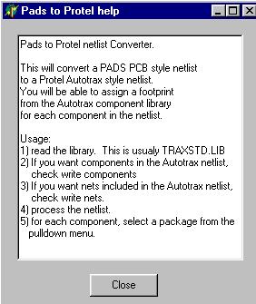
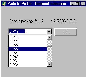
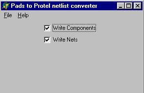
PADS to Protel Netlist converter
Cadcentric (Make rs274x gerbers from rs274d gerbers, and other utilities)
Gerber DRC
PCB Rotator
PAD Array
Contact me
download CADCENTRIC
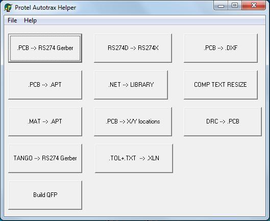
This is a collection of utilites which I have created as needed over the last 20 years.
- Cadcentric - creates a list of component positions, board side, and rotation. I created this to generate programming files for an assembly houses auto placement equipment. All of the selections on cadcentrics main form are for this function.
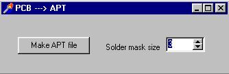
- PCB --> APT - This reads a PCB file, and generates a list of apertures which TRAXPLOT can use to generate gerbers. Be sure to set the soldermask oversize setting before creating the apertures.
- MAT --> APT - This reads the .MAT file created by TRAXPLOT and creates a neat, sorted aperture file (each entry only listed once).
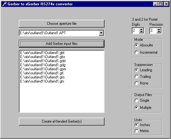
- GERBER --> XGERBER - This is the most usefull utility in this program. This combines an aperture file, and RS274D gerber file/s into one / many RS274X embedded aperture gerber files.
- DRC --> PCB - Highlights DRC violations on the PCB.
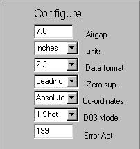
- PCB --> XGERBER - Replaces Traxplot. Directly generates RS274X gerbers from .PCB. Adds dimentions to .GDD file. Embeds tool sizes in .TXT file. Creates external poured fills by outlining the area to be filled with a .001 trace.
- .NET --> LIBRARY - Creates a .LIB file with all of the components found in a net list. Looks through all existing .LIB files to get components.
- .Build QFP - Creates a .PCB file which has pads for a QFP part. Pins are numbered. You must then define as a block and save as a component after loading file.
This is a major re-write of the x-Gerber generation code. I re-wrote the routine which writes each Gerber element to the output file. This greatly simplified the function, and seems to have corrected some issues.
I also re-wrote how copper pours are created. The old version used x-Gerber polygons, with cut outs for pads. It did not support tracks inside of copper pour areas. The new method writes all the the copper pours as x-Gerber polygons, then creates a negative layer in the same file to create room for pads and tracks. Finally a third positive layer is added to the file with the pads and tracks. You still define a copper pour by drawing a border around it with a .001 track. Any multilayer pad will be attached to the pours on both sides of the board if either direct or relief is selected. Thermals (reliefs) are handled as they should be. Any surface mount pad "tagged to power" or "tagged to ground" will be attached to the pour on that side of the board with a thermal/relief. There is a new setting in the choose PCB file screen to define the spacing between pads/tracks and the surrounding copper pour.
In addition, the select PCB form popups now appear over the form, instead of in the middle of the screen, and the select PCB form remembers where it was last positioned.
This looks good in GC_Prevue, but I have not fabricated a board yet.
NEW Added for version 2.5
PCB --> XGERBER -
Replaces Traxplot.
Directly generates RS274X gerbers from .PCB.
Adds dimentions to .GDD file.
Embeds tool sizes in .TXT file.
Creates .CSV BOM reports.
Creates external poured fills by outlining the area to be filled with a .001 trace.
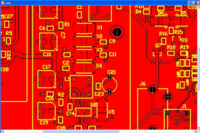
Sample showing poured fill and
dimentioned
.gdd.
NEW Added for version 2.4
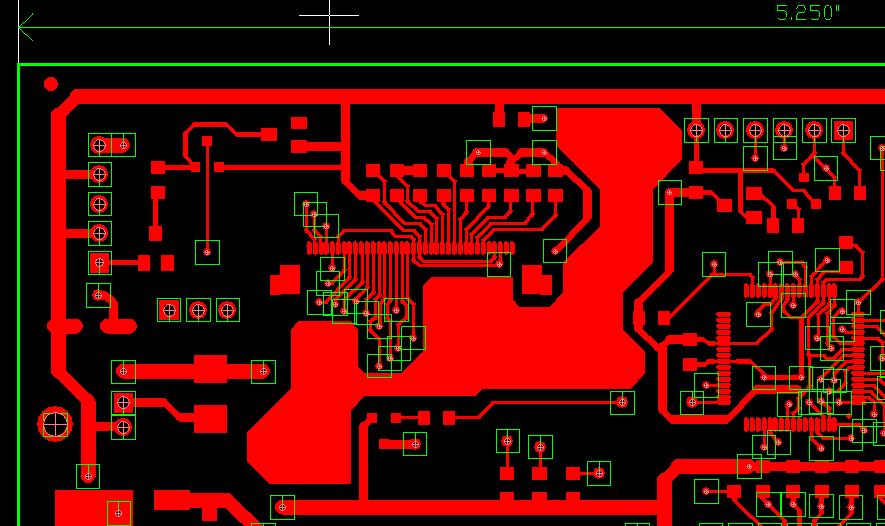
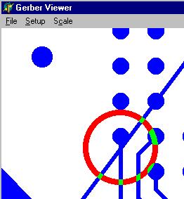
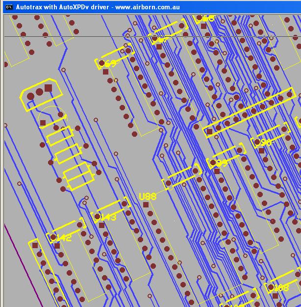
There is now a feature to read the DRC file generated by Autotrax, and highlight the prblem areas in the PCB file.
Much easier than creating printouts and going to each XY location to find the clearence violations.
This can be placed in a new pcb file, or added to the keepout layer for the acutual design:
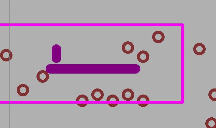
Here is an image showing a clearance violation:
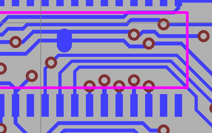 +
+I let autotrax generate a DRC file, then run the DRC --> PCB function.
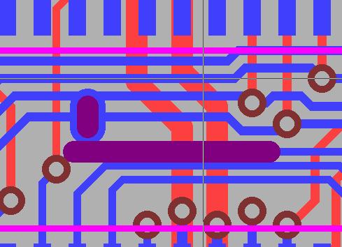
Here is an image showing the highlights created on the keepout layer:
And here is the combined image:
I will be adding online help for this program eventualy.
GERBER DRC
This program has been abandoned as there are better free options avalable online.
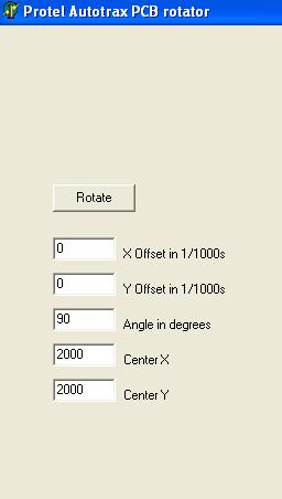
download PCB Rotator
This program will rotate an entire PCB.
The Sample shown here is the "bigdemo.pcb" sample supplied with autotrax rotated 25 degrees.
This program is great if you need a rotated component.
1) Place the component you need by itself in a new pcb.
2) Rotate the new PCB with this program.
3) Block read the rotated PCB into your design and you have a rotated component.
Of course, you can also rotate sections of your final design, or the entire PCB.
Shortcomings:
1) Text strings are still horizontal or vertical.
2) Square pads are still horizontal or vertical.
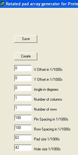
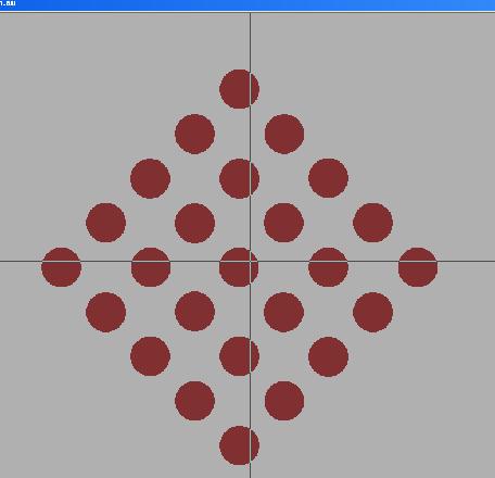
download PAD Array
This program generates an array of pads at any angle..
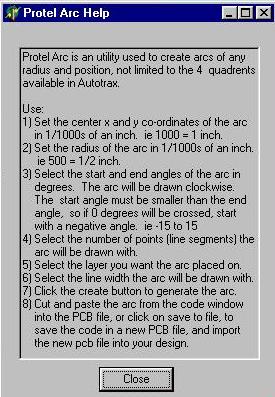
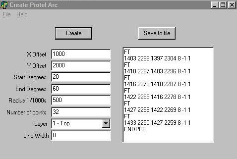
download Protel Arc Maker
download PADS to Autotrax Netlist converter
| Contact me les@hildenbrandt.com |
 |
|