Primer on PCBs, Gerber photoplotters, RS274 Gerber files, and RS274X Gerber files
What are Gerber files? What are RS274X gerber files? How
are PCBs made?
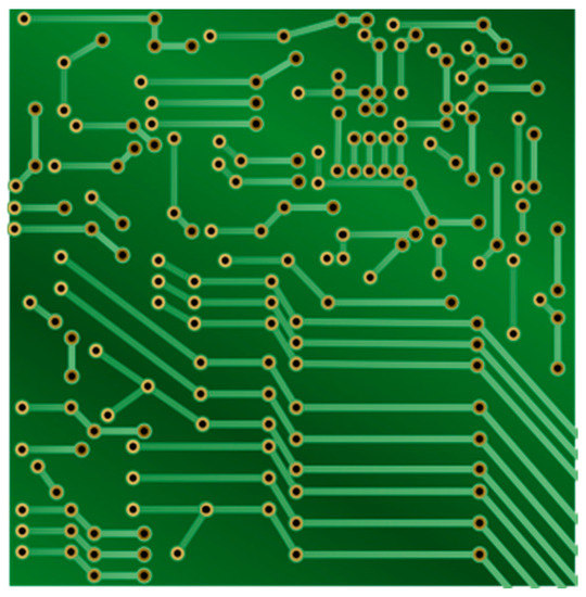
This is a printed circuit board (PCB). It's purpose to to hold
and connect electronic devices to complete a circuit. You can
see in the image that there are holes in the board where component
leads are insrted and soldered in place. There are what look
like green lines connecting these holes. These green lines are
copper. They appear green because they are covered with solder
mask. Solder mask is a coating to prevent solder from sticking
to the copper under the mask. There are openings in the mask
where we want solder to stick.
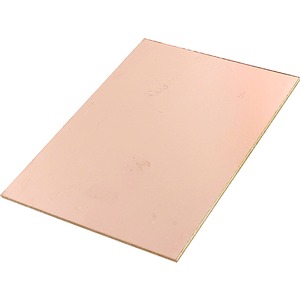
PCBs start life as a bare board, usualy fiberglass, covered with a
solid layer of copper.
To turn that blank board into a usable PCB, we need to drill the
holes, and remove the copper where we dont want a connection.
The copper is removed with an acid such as ferric chloride. To
prevent the copper from being removed where we want a connection, a
acid resitant mask is applied to the raw board. The entire
surface of the board is covered with a photo sensative mask. A
transparent negative image of our desired layout is placed on top of
the blank board. It is exposed to light, then developed.
This leaves the acid resitant mask only in the places we want
copper. When the entire board is submerged in acid, the copper
not coved with the mask is dissolved.
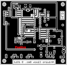
We are approching to topic this page is intended to cover, how is
that transparent negative made?
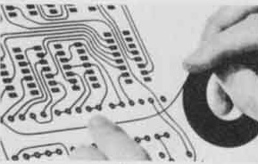
A long time ago, the designer would use drafting tape on paper (or
mylar). It was usualy done bigger that the desired board
size. Once the paper and tape design was finished, it would be
photographed and a correct size negative would be created.
This is a long and tedious process.
Now we use computers to design our boards, much easier. The first
photo plotters (printers) used to create the negative were made by
Gerber. These were very simple devices.
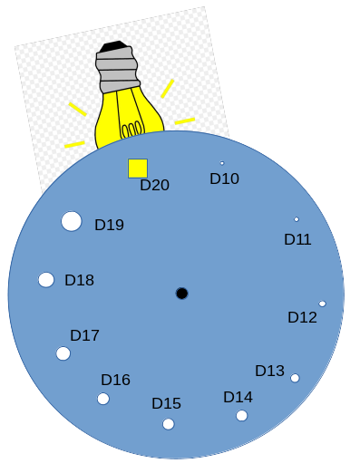
They had a metal disk with various sized and shaped holes.
Behind one of the holes was a light bulb. The computer could
instruct the plotter to rotate the disk to select which size and
shape hole was in front of the light bulb. The computer could
also turn the light bulb on or off.
The entire disk and light mechanism was on a x/y platform, and could
be moved under computer control.
A sheet of unexposed photographic film was placed under the
mechanism.
The plotter understood a very few commands, these are the most used:
- D01 - Turn the light on
- D02 - Turn the light off
- D03 - Flash the light (on then off)
- D10-1000 - Select which hole is on front of the light. The
number of choices was usualy well under 50.
- X - Y - Move the light to X, or Y, or XY position.
So a hole size / shape could be selected, the light could be
moved to a position, the light could be turned on, the light could
be moved to the next position, then the light could be turned off.
This works, but is awkward. For example, you want to draw a
track 0.020 inch wide, but you closest hole size is 0.010.
You would need to draw two lines side by side to make the correct
width track. If you want to make a copper area 2 inches by 3
inches, but your largest square hole in 0.050 inches, you need to
paint back and forth many times to get the desired image size of
the film. Round pads are worse, if you need to make a larger
round pad, you need to make many short lines around the circle,
maybe 360 (1 per degree) to draw the larger pad. As you can
imagine, this makes for very large Gerber files.
A board house I used in those days would provide an aperture list
that they supported, and I would need to generate my Gerber files
using those apertures.
Technology moves on, and Gerber photplotters changed to laser
photoplotters. The aperture disk was gone. The file
format stayed the same however. You could specify any number
of any size or shape apertures, so you always had the correct size
aperture for any feature on the board. The laser
photoplotter would convert alll of these commands to a raster
image, and print it all at once.
In this case, instead of the board house telling you what
apertures to use, you could create your own aperture list.
The laser photoplotter would simulate all of those apertures.
RS274X Gerber files include the aperture list as a header in the
Gerber file, so you no longer need a seperate aperture file.
There are many other improvements, but this is the reason the old
format gerber files are no longer accepted.
I hope this helps with understanding Gerber files.
Back to Autotrax page